Project Network Setup
Project Network Setup
Project Network Setup
_________________
"Well begun is half done."
– Aristotle
"Well begun is half done."
– Aristotle
"Well begun is half done."
– Aristotle
Project Introduction: Homelab for Advanced Network Security and SOAR Integration
This project centers around the design, implementation, and optimization of a homelab environment tailored to simulate and address real-world cybersecurity challenges. By leveraging a robust network foundation and integrating Security Orchestration, Automation, and Response (SOAR) tools, the goal is to create a scalable and secure platform for learning, experimentation, and professional portfolio development.
The network is segmented across two subnets (10.0.0.0/28 and 10.0.1.0/28) and anchored by a Windows Server acting as the gateway, with Active Directory, DNS, and DHCP configured to manage the domain infrastructure. The Elastic Stack serves as the cornerstone for centralized log management and visualization, while tools like Kibana, TheHive, and Elastic Endpoint Security provide robust incident detection, analysis, and automated response workflows.
Additionally, the project incorporates modern strategies for secure data routing, such as VPN tunnels and Cloudflare Tunnels, to safely integrate external honeypot data from TPot into the internal SOAR setup. We also address Vulnerability Management as well. This allowing for detecting, patching, and remediating vulnerabilities utilizing the Nessus scanner.
Ultimately, this project showcases not only technical proficiency in network administration and security orchestration but also the adaptability required to tackle dynamic challenges in cybersecurity operations.
This Project will align with NIST 800-53 and ISO/IEC 27001 for secure domain network deployment.
Project Network Diagram:
Project Network Diagram:

Hyper-V, vGW, and vSwitch Deployment
To begin, we'll start with a Windows Server 2022 .iso and image the physical infrastructure Dell Poweredge R390 (hostname VMHOST), which will act as the host machine for all further internally-hosted virtual infrastructure used within the lab. Mounting the .iso to removable media, we'll provision a fresh installation of the OS to the VMHOST server, opting for the standard desktop experience installation. Once we're booted, we'll install all available updates, navigate to Manage -> Add Roles & Features Wizard, and add the Hyper-V role to VMHOST.
To begin, we'll start with a Windows Server 2022 .iso and image the physical infrastructure Dell Poweredge R390 (hostname VMHOST), which will act as the host machine for all further internally-hosted virtual infrastructure used within the lab. Mounting the .iso to removable media, we'll provision a fresh installation of the OS to the VMHOST server, opting for the standard desktop experience installation. Once we're booted, we'll install all available updates, navigate to Manage -> Add Roles & Features Wizard, and add the Hyper-V role to VMHOST.
Next, we'll access the Hyper-V manager -> Virtual Switch Manager and create an external virtual switch that will virtualize our connection back to the external physical router, providing internet connectivity to the lab devices.
Next, we'll access the Hyper-V manager -> Virtual Switch Manager and create an external virtual switch that will virtualize our connection back to the external physical router, providing internet connectivity to the lab devices.

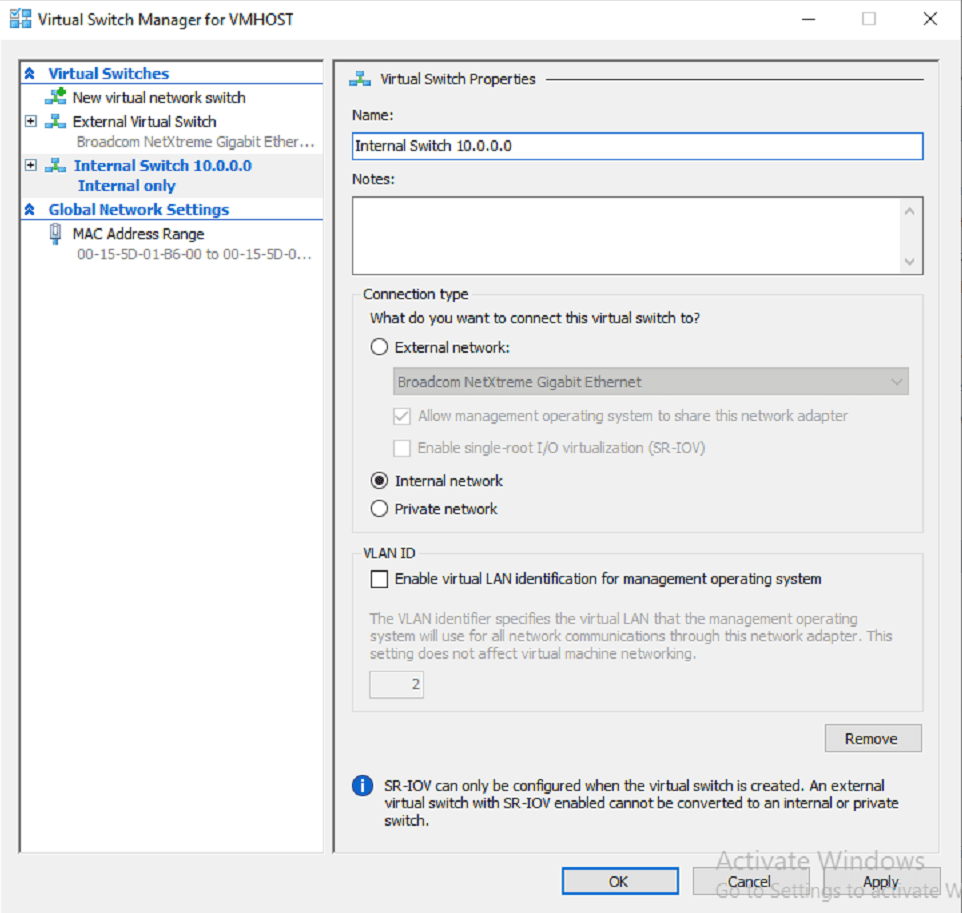
Next, we'll create a virtual switch to connect devices together on the internal subnet. This subnet will be for our first set of Windows devices that will be utilizing AD DS, and will be bridged at 10.0.0.0/28 on the vGW.
Next, we'll create a virtual switch to connect devices together on the internal subnet. This subnet will be for our first set of Windows devices that will be utilizing AD DS, and will be bridged at 10.0.0.0/28 on the vGW.
Now that we have a way to bridge internet connectivity to our VMs, we'll create our first VM that will act as the Gateway into the network. We'll want to do this for a couple reasons:
Subnet limitations on consumer routers
Further isolation to the lab-environment from the home network
More granular control as to how traffic moves and is routed through the lab environment
This segmentation approach aligns with NIST SC-7, emphasizing more secure subnets
Central location for routing between any subnets created within the lab
To begin, we'll navigate to our VMHOST server and create a new VM within the Hypervisor named "Gateway1". This VM is configured with another Windows Server 22 copy and is configured with 2 vCPUs, TPM, and has the capacity for two active connections with two vNICs (these will be bridged appropriately to the external (192.168.1.0/24) and internal (10.0.0.0/28) virtual switches). Once created, we'll connect, install the OS, run updates, then access the Server Manager where we will navigate to Manage -> Add Roles & Features Wizard to add Remote Access and Remote Server Administration Tools. We will then install the roles and restart the VM.

After relaunching, we'll now open Routing and Remote Access (RAS) and begin the Server Setup Wizard, configuring the use of NAT and LAN routing capabilities.
After relaunching, we'll now open Routing and Remote Access (RAS) and begin the Server Setup Wizard, configuring the use of NAT and LAN routing capabilities.

In order for our vRouter to know where to route traffic to a resource not available on the local subnet, it will need to be configured with a static route that instructs the gateway to route traffic to the external router. For simplicity, we can configure a static route with RAS to do just this.
Expanding the IPv4 settings in the left navigation pane, we can create a static route to allow for routing to the external gateway from requests from internal lab devices. Setting the interface of the Internal vSwitch (eth0), with a default route of 0.0.0.0 for the destination to apply to all egress traffic, the network mask of the external network, 255.255.255.0 class-c address, the IP address as the External Gateway (next-hop) address, with the default metric assigned.

We'll finally need to enable NAT functionality on the gateway in order for traffic to be correctly inbound and outbound to the lab. To configure this, we can simply right-click the NAT configuration listed below IPv4 and configure it for both the internal and external interfaces. This "double-NAT" configuration could cause issues for inbound services later, but we'll utilize other methods to route unsolicited inbound traffic throughout the lab-environment. This method supports NIST SC-5 recommendations for egress traffic control.
We'll finally need to enable NAT functionality on the gateway in order for traffic to be correctly inbound and outbound to the lab. To configure this, we can simply right-click the NAT configuration listed below IPv4 and configure it for both the internal and external interfaces. This "double-NAT" configuration could cause issues for inbound services later, but we'll utilize other methods to route unsolicited inbound traffic throughout the lab-environment. This method supports NIST SC-5 recommendations for egress traffic control.


With these configuration in place, our virtual gateway should now be able to effectively serve as the egress point of the lab, and route traffic in, or out of the homelab environment correctly.
With these configuration in place, our virtual gateway should now be able to effectively serve as the egress point of the lab, and route traffic in, or out of the homelab environment correctly.
With these configurations in place, our virtual gateway should now be able to effectively serve as the egress point of the lab, and route traffic in, or out of the homelab environment correctly.
II. DHCP Deployment
II. DHCP Deployment
We will now create another machine within our lab environment to act as the DHCP server (DHCP01).
We will now create another machine within our lab environment to act as the DHCP server (DHCP01).


After launching the DHCP01 VM, we'll run updates, navigate to Server Manager > Add Roles and Features to install the DHCP role onto the system.
We'll next specify the scope for the subnet that our vSwitch is bridged to, and our Gateway is set for
We'll next specify the scope for the subnet that our vSwitch is bridged to, and our Gateway is set for

After the installation of the DHCP server role has been completed, we'll define a new scope for the server. This will be for our first subnet where our AD DS machines will reside.
After the installation of the DHCP server role has been completed, we'll define a new scope for the server. This will be for our first subnet where our AD DS machines will reside.

We will next begin defining DHCP reservations, which will address NIST CM-8 asset management requirements. From the same DHCP Manager Snap-in within MMC, we'll expand IPv4, right-click "Reservations" And select "Create a New Reservation". We will then create a MAC-based DHCP reservation @ 10.0.0.3 for our DHCP Server.
We will next begin defining DHCP reservations, which will address NIST CM-8 asset management requirements. From the same DHCP Manager Snap-in within MMC, we'll expand IPv4, right-click "Reservations" And select "Create a New Reservation". We will then create a MAC-based DHCP reservation @ 10.0.0.3 for our DHCP Server.

We will then repeat the process, and set a DHCP reservation for our vGW, Gateway01 @ 10.0.0.1
We will then repeat the process, and set a DHCP reservation for our vGW, Gateway01 @ 10.0.0.1

Domain Controller Deployment
Domain Controller Deployment
The next VM that we'll need to setup for our AD DS subnet is our Domain Controller. From here, we can create and manage our AD DS Domain and enable the use of Domain Tools such as AD CS and ADUC.
To start, we'll access the hypervisor again on the VMHOST server and create another VM and name it DC01.

After creating the VM, we'll connect and start, install Windows, and run Updates.
After concluding, we'll set DC01 net adapter to use DHCP, and open Server Manager > Add Roles and Features, to add the Active Directory Domain Services Role
After creating the VM, we'll connect and start, install Windows, and run Updates.
After concluding, we'll set DC01 net adapter to use DHCP, and open Server Manager > Add Roles and Features, to add the Active Directory Domain Services Role

Next we'll set a new DHCP MAC-based reservation on DHCP01 for our Domain controller @ 10.0.0.2
Next we'll set a new DHCP MAC-based reservation on DHCP01 for our Domain controller @ 10.0.0.2

We'll now begin creating our local domain. Firstly, we'll promote DC01 to a Domain Controller in Server Manager by navigating to Manage -> "Promote this server to a Domain Controller". This will prompt the Active Directory Domain Services Configuration Wizard to appear, where we will select the option to "Add a new forest" and name our domain, "smmdevice.local"
We'll now begin creating our local domain. Firstly, we'll promote DC01 to a Domain Controller in Server Manager by navigating to Manage -> "Promote this server to a Domain Controller". This will prompt the Active Directory Domain Services Configuration Wizard to appear, where we will select the option to "Add a new forest" and name our domain, "smmdevice.local"

Continuing through our Domain creation, we'll specify the Domain controller as writable, and set a DSRM password. On the next two pages, we will not specify a DNS delegation, and we will leave the remainder of options as defaults
Continuing through our Domain creation, we'll specify the Domain controller as writable, and set a DSRM password. On the next two pages, we will not specify a DNS delegation, and we will leave the remainder of options as defaults

III. DNS Configuration
We'll now begin configuring our Forward and Reverse lookup zones on our AD Domain. After rebooting, we can access the Server Manager -> DNS -> DNS Manager, then we'll right-click on our DC01 server and click "Configure a DNS server" to open the Wizard.
We'll now begin configuring our Forward and Reverse lookup zones on our AD Domain. After rebooting, we can access the Server Manager -> DNS -> DNS Manager, then we'll right-click on our DC01 server and click "Configure a DNS server" to open the Wizard.

At the next page, we'll opt to create both a Forward and Reverse Lookup Zone. Creating a forward lookup-zone will allow us to utilize hostnames across the domain, and satisfies the requirements for NIST SC-12 for secure DNS Resolution
At the next page, we'll opt to create both a Forward and Reverse Lookup Zone. Creating a forward lookup-zone will allow us to utilize hostnames across the domain, and satisfies the requirements for NIST SC-12 for secure DNS Resolution

We'll then begin the creation of the forward lookup zone
We'll then begin the creation of the forward lookup zone

We'll set this zone as our primary as this is to be our Authoritative DNS Server, and we'll need to be able to make changes to the zone from DC01
We'll set this zone as our primary as this is to be our Authoritative DNS Server, and we'll need to be able to make changes to the zone from DC01

On the next page of the wizard, we will set the zone to replicate to all other domain controllers that we may deploy in the future.
On the next page of the wizard, we will set the zone to replicate to all other domain controllers that we may deploy in the future.

Next we'll create the Zone Name, which should match our root forest
Next we'll create the Zone Name, which should match our root forest

We'll run through the same configurations during the creation of the Reverse Lookup zone as well, until we reach the point in the wizard where we will need to specify the Network ID portion of the subnet that the Zone will be resolving addresses on. Since this is 10.0.0.0/28, our network address will be 10.0.0.0, or 10.0.0 for the Network ID
We'll run through the same configurations during the creation of the Reverse Lookup zone as well, until we reach the point in the wizard where we will need to specify the Network ID portion of the subnet that the Zone will be resolving addresses on. Since this is 10.0.0.0/28, our network address will be 10.0.0.0, or 10.0.0 for the Network ID

We'll then configure a forwarder for our DNS server for 8.8.8.8. Since all of our machines in the lab will be using this server as their primary DNS, it will need a forwarder configured in order to correctly route traffic that the DNS does not have a record for. For this, we'll use Google's public DNS
We'll then configure a forwarder for our DNS server for 8.8.8.8. Since all of our machines in the lab will be using this server as their primary DNS, it will need a forwarder configured in order to correctly route traffic that the DNS does not have a record for. For this, we'll use Google's public DNS

Finally, both Forward and Lookup Zones have been configured, and we can finalize the configuration, and close the Wizard

We'll then configure an A Record located within the Forward LookupZone to
We'll then configure an A Record located within the Forward LookupZone to

Then our Pointer record for the Reverse Lookup Zone
Then our Pointer record for the Reverse Lookup Zone

Now that DNS Resolution is confirmed to be successful, we can join the domain by hostname. To do so, on the Gateway01 machine, we'll run system.cpl from the Run Dialog, hit change, and enter the smmdevice.local domain into the Domain field. We'll authenticate with the Domain Administrator user.

After the records have been completed, and the Gateway joined, we can test the Forward Lookup Zone to verify that DNS Hostname resolution is successful. Before we can however, we'll need to allow unsolicited ICMPv4-in requests. To do so, we'll open Windows Firewall, navigate to Inbound Rules, where we can right-click the appropriate rule and click "Enable-Rule" This only allows for ping requests made from Domain devices to be resolved.
After the records have been completed, and the Gateway joined, we can test the Forward Lookup Zone to verify that DNS Hostname resolution is successful. Before we can however, we'll need to allow unsolicited ICMPv4-in requests. To do so, we'll open Windows Firewall, navigate to Inbound Rules, where we can right-click the appropriate rule and click "Enable-Rule" This only allows for ping requests made from Domain devices to be resolved.

Now that firewall rules have been updated (this process is repeated on the DC01 side as well), we can now test for ICMP traffic using the A record defined earlier.

And success! We will build upon this setup in other projects as required. For best practice, the DHCP server will also be domain-joined. This should serve as the basis for additional projects that are listed on the Portfolio site. Some will be on this subnet, and others on the 10.0.1.0/28 subnet, however, this network configuration will remain the same.
And success! We will build upon this setup in other projects as required. For best practice, the DHCP server will also be domain-joined. This should serve as the basis for additional projects that are listed on the Portfolio site. Some will be on this subnet, and others on the 10.0.1.0/28 subnet, however, this network configuration will remain the same.
And success! We will build upon this setup in other projects as required. For best practice, the DHCP server will also be domain-joined. This should serve as the basis for additional projects that are listed on the Portfolio site. Some will be on this subnet, and others on the 10.0.1.0/28 subnet, however, this network configuration will remain the same.